
    Big Fan Man
    Back to Blog
    HVLS FansExhaust Fans

    See the Air Before You Buy: CFD Airflow Modeling for HVLS Fans, Exhaust and Supply

    Oct 28, 20262 min read

    A big fan in an empty building is easy to picture. A big fan in your building, with racking, pallets and machines on the floor, is harder. That is where computational fluid dynamics (CFD) comes in. Before we supply and install a single fan, we can model your space and show you where the air will actually go.

    The example on this page models one 20 ft Hunter Industrial Titan, using Hunter's published AMCA-certified airflow (155,756 CFM at full speed, 380-480V) as the fan input.
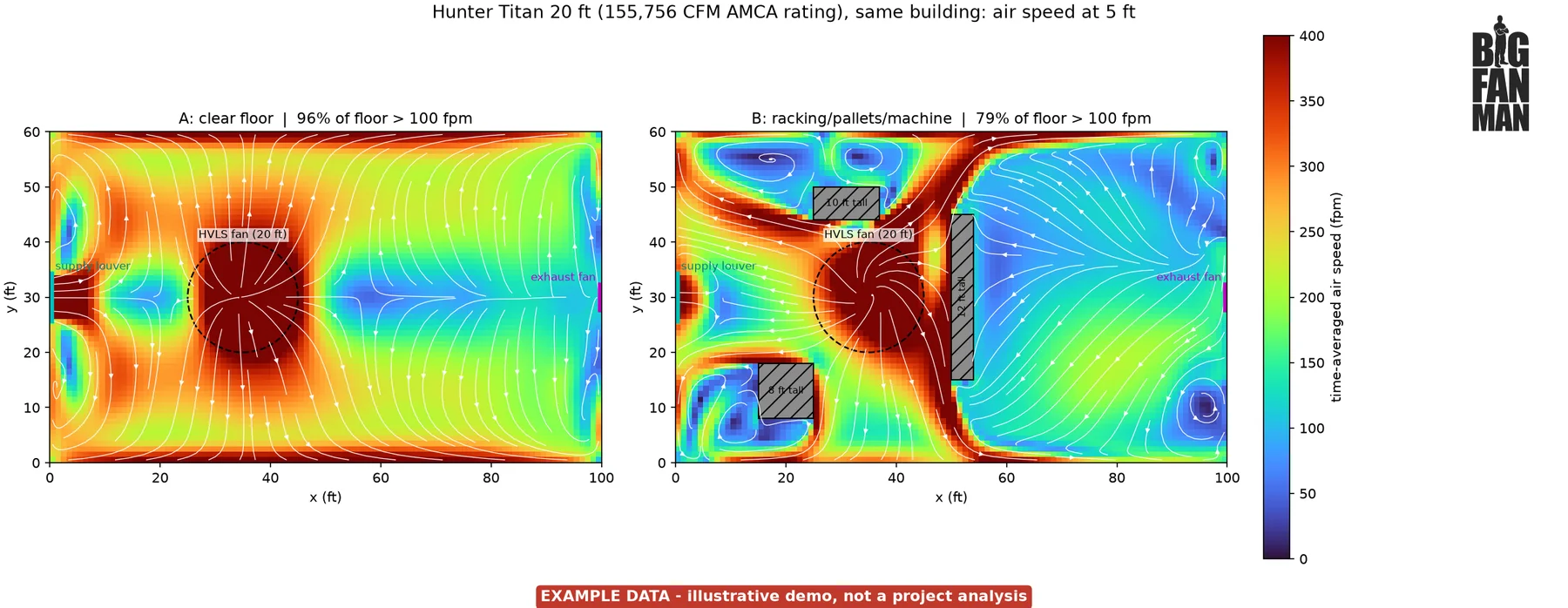
    Two overhead heat maps of air speed at 5 ft in the same 100 by 60 ft example room, with one 20 ft HVLS fan left of center. With a clear floor, nearly the whole room is above 100 fpm (96% of the floor). With a 12 ft rack row beside the fan, a 10 ft pallet stack and an 8 ft machine, the large area behind the rack row turns slow, and 79% of the floor is above 100 fpm. Labeled example data.
    Same fan, same building, different floor. Time-averaged air speed at 5 ft (the height where people work) under one 20 ft Hunter Titan (modeled from its AMCA-certified airflow). Left: clear floor. Right: the same room with a 12 ft rack row, a stack of 10 ft pallets and an 8 ft machine. Example data from an illustrative demo, not a project analysis.

    Why the floor matters more than you think

    An HVLS fan drives a large, slow column of air to the floor, where it spreads out as a wide floor jet. That floor jet is what cools people. Rack rows, stacked product and equipment block and turn it, leaving dead spots behind them. In this example, the floor jet hits the rack row 15 ft from the fan center and stops there, and the area behind the rack gets much less air.
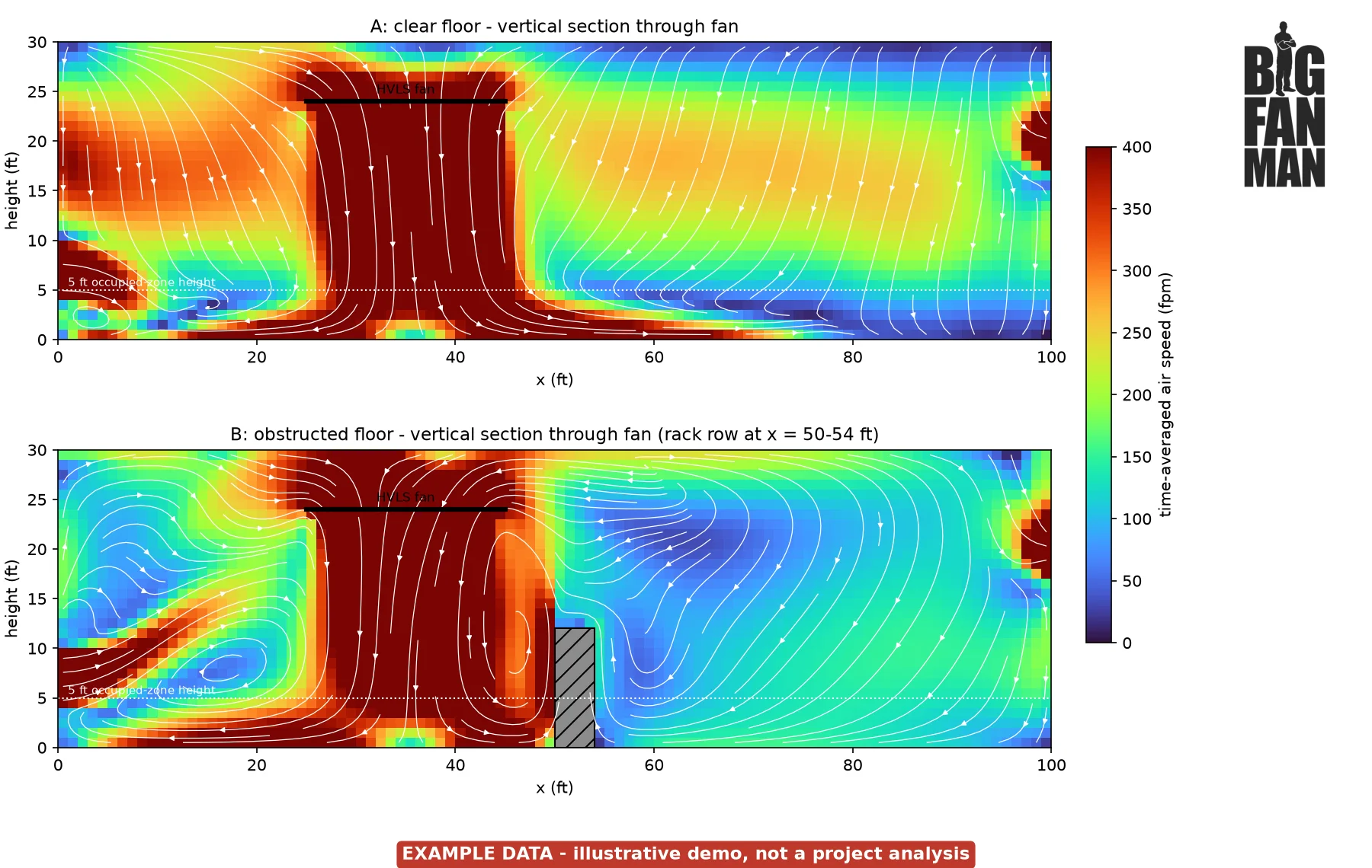
    Two side views cut through the center of the same example room. With a clear floor, the fan's column of air reaches the floor and spreads out along it in both directions. With the 12 ft rack row in place, the air spreading toward the rack stops at it and turns upward, and the air behind the rack is much slower. Labeled example data.
    Side view through the fan center. In the obstructed case (bottom), the 12 ft rack row stops the floor jet and turns it upward. Example data, illustrative only.
    Example demo resultA: clear floorB: obstructed floor
    Open floor area with air speed above 100 fpm at 5 ft~96%~79%
    Distance from fan where the average floor-level (1 ft) speed falls below 200 fpm~58 ft~32 ft
    Average air speed, floor to 6 ft~309 fpm~223 fpm

    Illustrative example room only. Not a Hunter or Big Fan Man performance claim; results depend on layout.
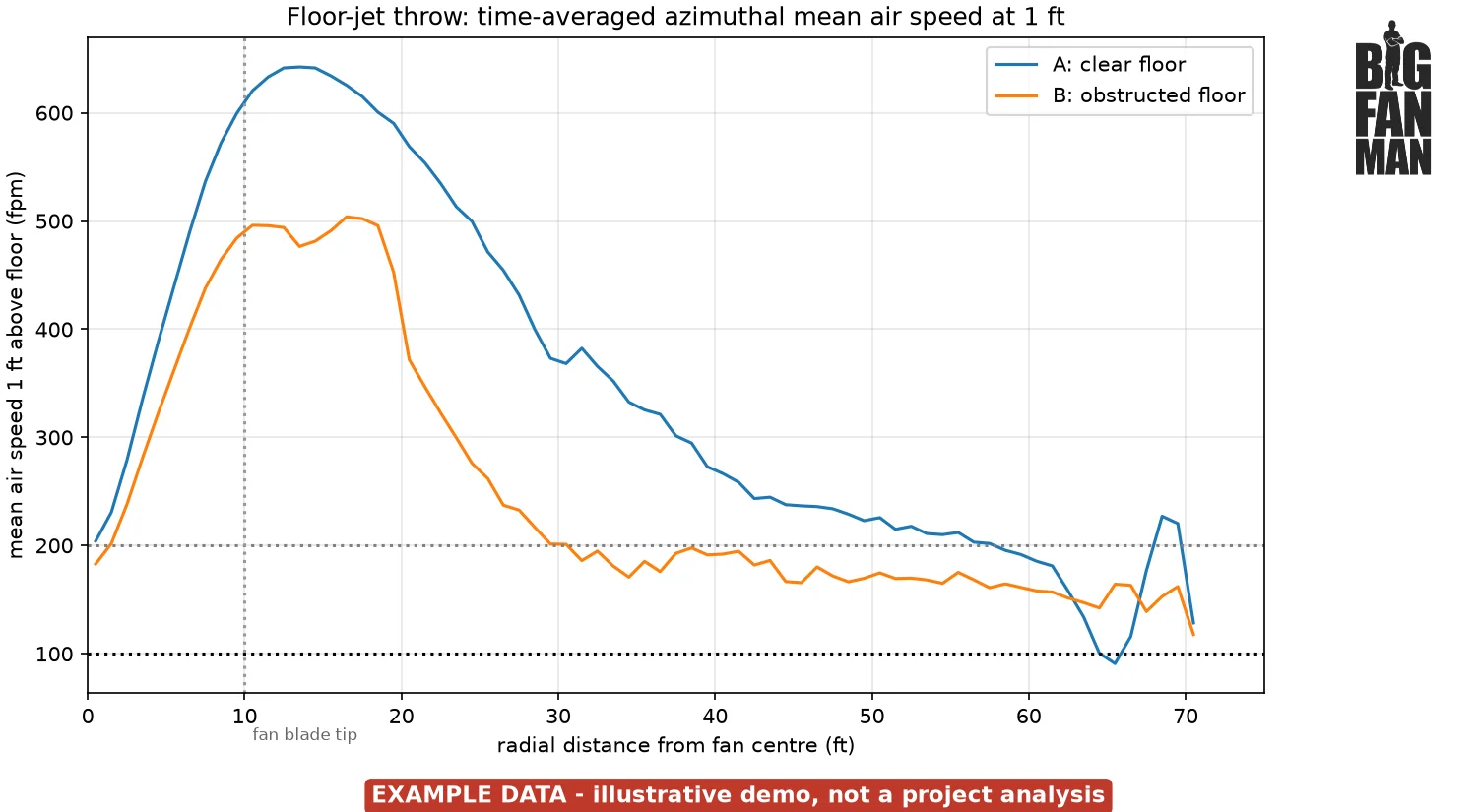
    Line chart of average air speed 1 ft above the floor against distance from the fan center. The clear-floor line peaks near 640 fpm about 13 ft out and stays above 200 fpm to about 58 ft. The obstructed-floor line peaks near 500 fpm and drops to about 200 fpm by 30 ft. Labeled example data.
    Average floor-level air speed vs. distance from the fan, time-averaged. Example data, illustrative only.

    What the model shows that you may not expect

    At working height, air near a wall exhaust fan can move away from it.
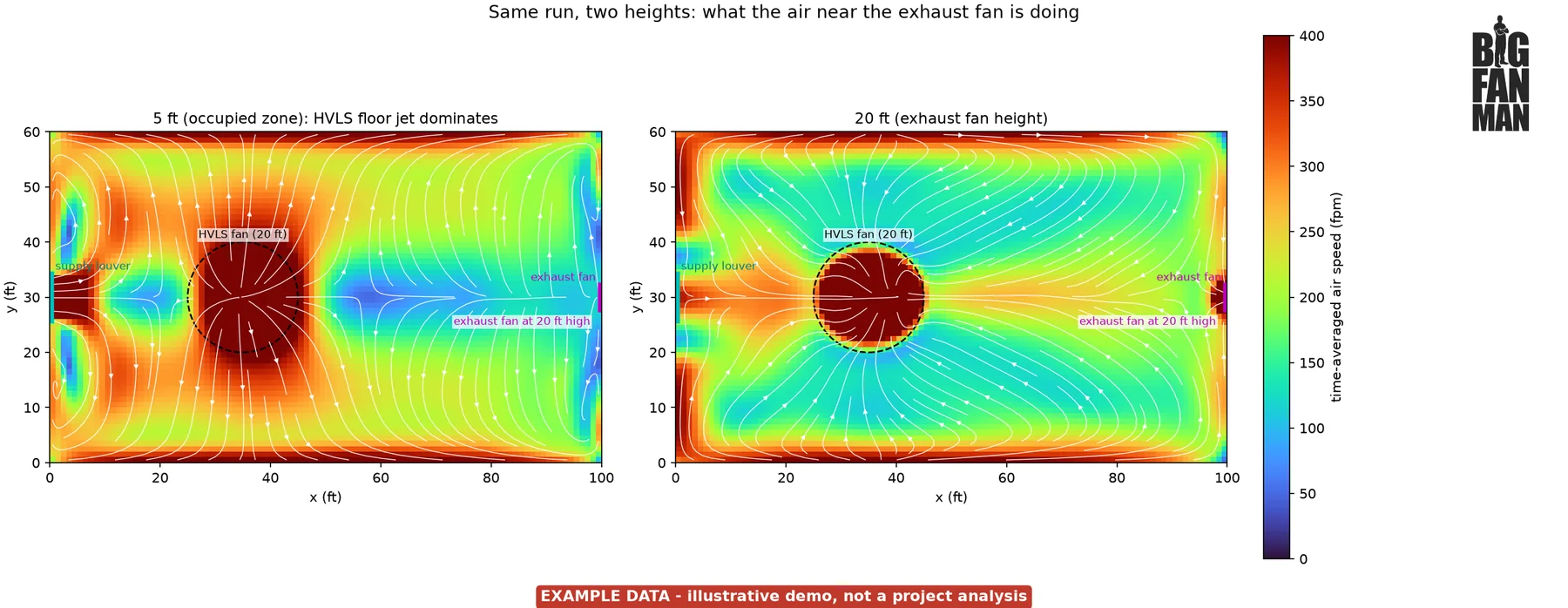
    Two overhead heat maps from the same run. At 5 ft, air spreads out from the HVLS fan across the whole room, and near the exhaust fan on the right-hand wall it turns along the wall instead of into the fan. At 20 ft, the height of the exhaust fan, the exhaust's pull shows only as a small spot at the opening, while air across the rest of the room is drawn toward the HVLS fan. Labeled example data.
    Same run, two heights. At 5 ft (left), the HVLS floor jet sets the direction of the air, even near the exhaust wall. At 20 ft (right), air turns toward the exhaust fan only close to the opening. Example data, illustrative only.

    An exhaust fan pulls air in from every direction, so its pull falls off with the square of distance. In this example, air moved toward the 20,000 CFM exhaust at more than 50 fpm only within about 10 to 15 ft of the opening.

    An HVLS fan pushes a focused jet that holds together. It drives a building-wide loop: down to the floor, out to the walls, up and back across the ceiling. At working height, that loop sets the air direction, even right below the exhaust fan. An exhaust fan does not pull air across the whole building. It controls how much air leaves, while supply openings and HVLS fans control where air moves inside. With the HVLS fan off, air mostly runs straight from the supply louver to the exhaust.

    • Exhaust: place it where heat, fumes or dust collect.
    • Supply: use openings and louvers to set the fresh-air path.
    • HVLS: place fans so their loop works with that path.

    What you get from an airflow study

    • Fan placement you can see, so the floor jet reaches people, not racking.
    • Exhaust and supply layouts that move air where it's needed.
    • Clear pictures for owners and safety teams before money is spent.

    Big Fan Man supplies, distributes and applies HVLS fans, wall and roof exhaust and supply fans, and creative air movement solutions.


    Related products: HVLS Industrial Fan

    Request a free airflow study

    Send us your building size, a rough floor layout and what you're trying to fix (heat, stale air, fumes or condensation). We'll show you what the air is doing and what we recommend.